- Full Atomistic MD
- Optical / Electrical / Magnetic
- Materials Science
![]() User Only
User Only
Optical Properties
Light can permeate a material and excite its electrons to produce an induced electric field. The interaction between the light and the induced electric field causes the light to refract. The ratio of the speed of light when permeating a material to the speed of light in a vacuum is called the refractive index. Different directions of light can permeate through different parts of the materials with different refractive indices. This can cause the speed of the light to differ depending on the surface it excites, which is a phenomenon known as birefringence.
Birefringence has a negative effect on optical materials such as those used in compact discs, plastic lenses, and optical film. For polymers in an irregular state such as an amorphous state, there is no directionality, and so the polymer becomes a uniform medium to the light, thereby avoiding birefringence. However, when the material is in a melted state (e.g., for injection molding), this will cause polymer molecular orientation. This oriented state will cause birefringence (orientation birefringence) due to the difference in the refractive index of direct polarized light moving toward the oriented structures at a particular direction versus the refractive index of the direct polarized light that bisects each other toward the oriented structure.
When light permeates a material that has birefringence properties, the light will separate into two beams that both oscillate in the vertical direction but have differing speeds. These will cause the imaging point to focus improperly, thus reducing the imaging performance. For this reason, when such polymers are used as optical devices for raw material such as compact discs or optical film, it is necessary to control the optical properties of these polymers, most importantly the arrangement of the polymer chain, which has a direct influence on birefringence (orientation birefringence).
Here, we have used the MD engine COGNAC to compute orientation birefringence by calculating the polymer uniaxial elongation properties. The substances used for these calculations were polystyrene, due to its negative birefringence properties, and polycarbonate, due to its high birefringence properties during orientation.
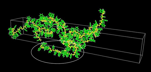 Figure 1. Polystyrene Uniaxial Elongation Simulation
Benzene Ring Plane Orients Perpendicular to the Direction of Elongation
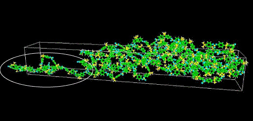 Figure 2. Polycarbonate Uniaxial Elongation Simulation
Benzene Ring Plane Orients Parallel to the Direction of Elongation
By examining the structure of the elongated polymers, we can observe that both polymers stretch along the elongation path (Z-axis). For polystyrene, the benzene ring plane is oriented perpendicularly to the Z-axis. However, for polycarbonate, the benzene ring plane is oriented parallel to the Z-axis. Because benzene rings contain ƒÎ electrons that move easily, the refractive index of the ring plane direction is high. The refractive index is believed to decrease if the ring plane is oriented perpendicularly. It is for this reason that polystyrene shows a negative birefringence when the benzene ring plane is oriented perpendicular to the elongation direction. Polycarbonate, when its benzene ring plane is parallel to the direction of elongation, shows a positive orientation birefringence.
 Figure 3. Orientation Birefringence of Various Plastics
Figure 3 shows the orientation birefringence with respect to the cell elongation ratio for PC (polycarbonate), PS (polystyrene), PC-and-PS blends, and PMMA (polymethylmethacrylate). PC shows a positive value, PS shows a negative value, and a value of nearly zero was obtained for PMMA. These results show trends that approximately replicate experimental results. A compatible PC-and-PS blended system also obtained a value approximately equal to zero. By creating a compatible polymer blend of substances with both a positive birefringence and negative birefringence, we can reduce the birefringence properties.
 Figure 4. Polycarbonate Derivatives
 Figure 5. Orientation Birefringence of Polycarbonate Derivatives
- Reference
- [1] Miyazaki, Togawa, Masubuchi, Molding Process '05, IV-312, pp 267-268, (2005)
- [2] Iwashimizu, Okubo, Ozawa, Kimizuka, Molding Process Symposium '06, C-201, pp 107-108, (2006)