- Full Atomistic MD
- Other methods
- Small molecule penetration / diffusion / adsorption
- Materials Science
Gas Solubility Coefficient and Free Volume
The permeability coefficient P derived from the gas permeability (gas barrier properties) of a polymer material was evaluated by multiplying the solubility coefficient S by the diffusion coefficient D. When using MD to calculate the diffusion behavior of gas molecules within the polymer, using the solubility coefficient and system free volume while setting the number of gas molecules and default installation sites will produce results close to actual phenomena.
Using EVMS (Evaluated Volume Map Sampling), the solubility coefficient can be estimated ([1]-[3]), but be sure to create the matrix component structure via NPT-ensembled MD beforehand. Compartmentalize the region, then arrange the test particles into each compartment of the given size. By evaluating changes in the energy of this system, the candidate installation site for the gas molecules can be selected (where ΔE < 0). Lastly, evaluate the solubility coefficient S using the in-energy changes by placing the actual gas molecules into the candidate position.
A cis-polyisoprene molecular structure (100 for the degree of polymerization) was created using the J-OCTA COGNAC modeler. An amorphous structure was created using VSOP at 1 atm at 100属C. Figure 1 shows the distribution where ΔE < 0 after inserting test particles with a diameter of 2.75 Å. This location will be the candidate installation site for the gas molecules. Furthermore, by adjusting the size of the test particles, the free volume can be evaluated.
The solubility coefficient S obtained from the energy changes when placing carbon dioxide molecules into all candidate positions is 4.23E-06 [cm^3 (STP)/(cm^3 Pa)] (STP stands for standard temperature and pressure). These are reasonable values when compared to the experimental data values.
We have also created a solver for the EVMS method. It is possible to consider the LJ potential and electrostatic interactions when performing these energy calculations. Please contact us for details.
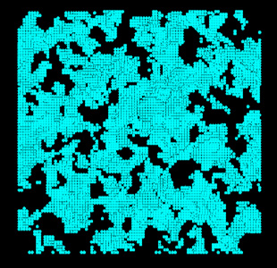 Figure 1. Candidate Installation Site of Gas Molecules Within Polyisoprene (Projection on XY Plane)
In actuality, only a limited number of positions can be used in which the energy changes for the placed gas molecules becomes negative (the position where the solubility coefficient can be properly evaluated).
- Reference
- [1] Mitsuhiro Fukuda, Journal of Chemical Physics, 112, 478, (2000)
- [2] Yoshinori Tamai et al, Macromolecules , 28, 2544, (1995)
- [3] Florian Muller-Plathe, Macromolecules , 24, 6375, (1991)