- Full Atomistic MD
- Interface / Phase Separation / Particle Dispersion
- Materials Science
[Analysis Example] Simulation of the deposition of film
MD simulation of the deposition process targeting OLEDs
Objectives and methods
Film formation by vapor deposition is a commonly used method for creating organic devices such as organic EL (OLED). It is known that the orientation of the molecules in the vapor-deposited film changes depending on the shape of the molecules, which in turn affects the device properties [1].
In this case study, we simulated the deposition process in order to analyze the shape of molecules used in organic devices and their orientation in the film. We simulated the deposition process by performing MD calculations on a base (Ag slab) with repeated molecular configurations.
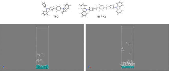
The molecules used in the calculations are called TPD and BSP-Cz, the latter of which has a more linear shape. For the force field, we used UFF for the molecules and the parameters reported in the reference [2] for Ag. The simulation was performed at a temperature of 300 K. The final deposition film consisted of 100 molecules.
 Figure 1. Top: Two types of molecules used in the calculations.Bottom: TPD deposition simulations ((left) early, (right) late).
Analysis Results
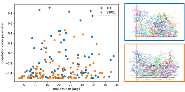
Figure 2 shows the structure of the vapor-deposited film of two kinds of molecules created by the deposition simulation, and the results of analyzing the orientation of the molecules in the film.
The orientation order parameter, \(P\), is expressed by the following equation: \(P=1\) means that the alignment is parallel to the reference axis, and \(P=-0.5\) means that the alignment is perpendicular to the reference axis. In this case, we used the z-axis as the reference axis to calculate the orientation order parameter \(P\) for each molecule, so we know that \(P=-0.5\) indicates an alignment parallel to the substrate.
\(P = (3 \cos( \theta )^{2} - 1)/2\)
As a result of the analysis, we can see that the BSP-Cz is more likely to be perpendicular to the Z-axis (parallel to the substrate).
 Figure 2. Left: Results of analysis of orientation order parameters.
Right: Structure of the deposited film of each molecule (Top: TPD, Bottom: BSPCz). )
- Reference
- [1] D. Yokoyama, Journal of Materials Chemistry, 21, 19187–19202, (2011)
- [2] H. Heinz, et al., J. Phys. Chem. C, 112, 17281–17290, (2008)


