RVE analysis function in J-OCTA
Modeling the micro /meso structure of composite materials and finite element analysis
One of the methods for predicting the properties of heterogeneous materials such as composites is the Representative Volume Element (RVE) method. RVE is a structure cut out of the smallest unit that can express macroscopic material properties, which can be reproduced from CT images of the actual material or created as a virtual structure using simulation and modeling software. RVE analysis mainly targets materials with dispersed or oriented structures of microparticles or fibers with spatial scales ranging from 100 nanometers (several tens of nanometers depending on the material) to 100 micrometers. The finite element method, finite difference method, particle method, etc. based on continuum models are applied as a computational method.
J-OCTA provides the following two RVE functions;
- “RVE modeler” to create a virtual RVE by specifying filler shape and volume fraction
- “The interface to Ansys LS-DYNA” to create a mesh of microstructures created by other modules of J-OCTA, and to support Ansys LS-DYNA input file creation and execution.
RVE modeler
The features of J-OCTA RVE modeler is to create models with complex shape fillers, highly filled structures, and models that take into account the interaction between fillers. Numerical experiments that create and analyze various structures with different filler shapes, volume fractions, and combinations support the design of composite materials.
RVE Modeler can be used to create models for VSOP-PS, an engine for materials process simulation using particle methods, and also be used to output the created models as mesh data to be passed to finite element and finite difference method software such as J-OCTA MUFFIN,Digimat-FE, and Ansys LS-DYNA.
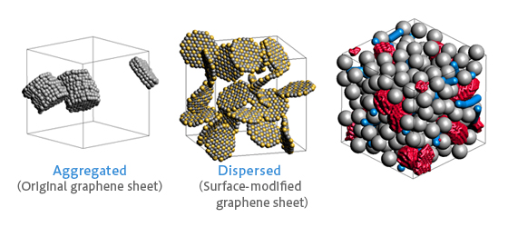 Figure.1 Example of model creation considering interaction between fillers
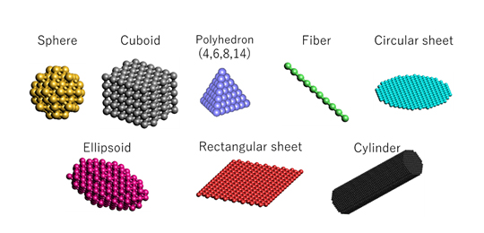 Figure.2 Examples of filler shapes that can be placed
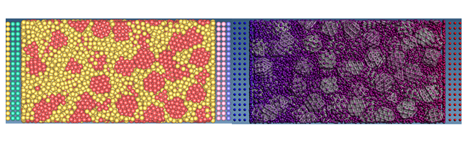 Figure.3 Left: Filler-filled polymer model created by RVE modeler, Right: heat conduction analysis result by VSOP-PS, particle method
The interface to Ansys LS-DYNA
The function of interface to Ansys LS-DYNA in J-OCTA outputs voxel meshes based on the phase-separation structure of SUSHI (SCF) and DPD calculation results, and the virtual structures created using RVE modeler, and executes Ansys LS-DYNA after assigning material settings and calculation conditions. Ansys LS-DYNA is a useful tool for analyzing various phenomena with its many material models and functions, but despite its versatility, it can be a hurdle for those new to this field of analysis. In this function, only the setting items necessary for RVE analysis are extracted, allowing even beginners to easily set up and perform analysis.
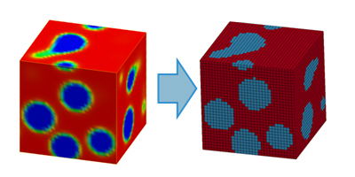 Figure.4 SUSHI Outputs voxel meshes from 3D density distribution
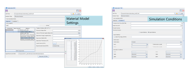 Figure.5 A settings screen for the Ansys LS-DYNA interface function