- DPD / Mean Field
- Interface / Phase Separation / Particle Dispersion
- Materials Science
[Analysis Example] Simulation of phase separation process in polymeric membranes
Evaluation of the NIPS (Non-Solvent Induced Phase Separation) process using mean-field model
Solvent evaporation and phase separation are important in the production process of polymeric membranes. Simulations are applied to evaluate the effects of interactions, initial conditions, etc. on the internal structure of the membrane.
Dissipative particle dynamics (DPD), coarse-grained MD and mean-field methods were applied in previous J-OCTA and OCTA cases targeting Directed Self-Assembly (DSA) [1], electrode slurry coating [2] and spin coating [3].
NIPS (non-solvent induced phase separation) is a technique for producing fine porous membranes. Several simulation studies have recently been published. Hydrodynamic effect[4], DPD [5], multiscale calculations including SCFT [6], glass transition of polymer components [7,8], viscoelasticity [9] and block copolymers [10], see the respective references for details.
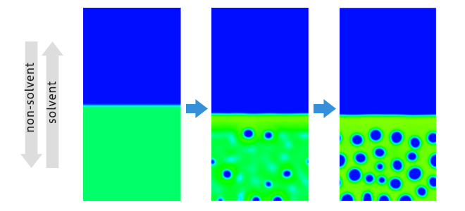
Here we present the simplest two-dimensional application of the mean-field calculations included in MUFFIN: the calculations are based on Flory Huggins' free-energy model and the parameters are set based on the references [4][6]. As shown in Fig. 1, a non-solvent is set in the upper half of the domain and a membrane with a mixture of polymer, solvent and non-solvent is set in the lower half. When the dynamics calculation is started, the non-solvent permeates the membrane on the lower side and, conversely, the solvent in the membrane diffuses to the upper side. As the polymer is soluble in the solvent but not in the non-solvent, phase separation occurs.
Using these calculations as a base, it is possible to include effects such as those discussed in the various references.
 Fig.1. Time evolution of phase separation in the polymer film considering NIPS process.
Green and blue region represents polymer and non-solvent component respectively.
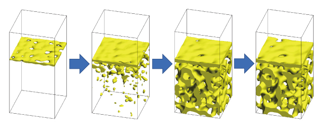
Fig.2 shows the calculation results for the 3D model. Following reference [8], concentration dependence was given to the motion (mobility) of each component. In particular, glass transition is applied to the polymer component. Holes are observed on the surface of the membrane (skin layer), showing a behavior similar to that of real materials.
 Fig.2. Time evolution of the NIPS process, considering concentration dependence of the mobility of each component, and glass transition of the polymer component (3D model).
Yellow region represents the polymer component.
- References
- [1] https://www.j-octa.com/cases/caseA26/
- [2] https://www.j-octa.com/cases/caseA36/
- [3] https://octa.jp/components/muffin/
- [4] Soft Matter,13, 3013, (2017)
- [5] J. Membrane Sci., 599, 117826, (2020)
- [6] (in Japanese) https://unit.aist.go.jp/cd-fmat/ja/c-dmd/ja/freport/contents/fr220118_3-07.pdf
- [7] ACS Macro Lett., 9, 1617-1624, (2020)
- [8] J. Membrane Sci., 619, 118779, (2021)
- [9] J. Chem. Phys., 154, 104903, (2021)
- [10] ACS Appl. Mater. Interfaces, (2023) https://doi.org/10.1021/acsami.3c03126


